jeudi 26 avril 2018

LCD Controll with I2C


hey guysin this tutorial we ll show you another typeof using of  LCD device . We ll use the protocol I2C, this protocol uses only 2 pins instead of 16 (number of pins of LCD device).

I2C (Inter-Integrated Circuit) is a short distance serial interface that requires only 2 bus lines for data transfer. It was invented by Philips in 1980’s, originally to provide easy on-board communications between a CPU and various peripheral chips in a TV set. Today, it is widely used in varieties of embedded systems to connect low speed peripherals (external EEPROMs, digital sensors, LCD drivers, etc) to the main controller.


the vast majority of I2C LCDs are basically the same because they use the same 8 bit I/O expander chip PCF8574. There are a various other expander but it is important  to know the expander we working with.


to work PCF8574 an arduino library is needed for setting the setting ofthis device
you just need to import itto arduino library

PS: if you are using another I2C expander you ll have problems with your LCD


after import it you need to restart your Arduino IDE and then u can test your module by using the sketch below


connecting lcd module to arduino


samedi 14 avril 2018

How to connect HC-05 to an another HC-05 or HC-06

HC-05 ==> HC-05 || HC-06


hi guys it's been a while. nice to see you again and  i hope you are fine.

today we gonna show you how to connect 2 bluetooth devices and have a data transfer between them


first of all we'll explain differences between HC-05 and HC-06


Bluetooth is a wireless technology standard for exchanging data over short distances (using short-wavelength UHF radio waves in the ISM band from 2.4 to 2.485 GHz) from fixed and mobile devices, and building personal area networks (PANs). Range is approximately 10 Meters (30 feet).


  • HC-05 is a more capable module that can be set to be either Master or Slave.
  • HC-06 is a Slave only device. (It looks physically just like the HC-05).(Note: Now HC-06 not cheaper)
  • These small ( 3 cm long) modules run on 3.3V power with 3.3V signal levels, They have no pins and usually solder to a larger board. (See example below)
  • The module has two modes of operation, Command Mode where we can send AT commands to it and Data Mode where it transmits and receives data to another bluetooth module.
  • "Breakout" Boards that make these easy to use are available and recommended. These mount the sub-module like that shown on the right on a slightly larger board. NOTE: Sellers often label them "HC-05" or "HC-06", but they have some other model number on the reverse side. Most of these boards support operation at 5V power and interface to 5V Arduino signal levels with some technique of level shifting.

HC-05 : 


HC-05 PinOut (Right) :
  • KEY: If brought HIGH before power is applied, forces AT Command Setup Mode. LED blinks slowly (2 seconds)
  • VCC: +5 Power
  • GND: System / Arduino Ground
  • TXD: Transmit Serial Data from HC-05 to Arduino Serial Receive. NOTE: 3.3V HIGH level: OK for Arduino
  • RXD: Receive Serial Data from Arduino Serial Transmit
  • STATE: Tells if connected or not


The module has two modes of operation, Command Mode where we can send AT commands to it and Data Mode where it transmits and receives data to another bluetooth module.

The default mode is DATA Mode, and this is the default configuration, that may work fine for many applications:

  • Baud Rate: 9600 bps, Data : 8 bits, Stop Bits: 1 bit, Parity : None, Handshake: None
  • Passkey: 1234
  • Device Name: HC-05


Bluetooth Master Mode:To configure the module as Bluetooth Master and to pair with another bluetooth module follow these steps. First we need to put the module into command mode as above by pulling the CMD pin high before power on. (Use the BlueToothCommandUtility for this.)
Enter these commands in order:


we must set those AT commands to every devices we'll use
  • AT+RMAAD Clear any paired devices
  • AT+ROLE=1 Set mode to Master (=0 set mode to slave).
  • AT+RESET After changing role, reset is required
  • AT+CMODE=0 Allow connection to any address (I have been told this is wrong and CMODE=1 sets "any address"
  • AT+INQM=0,5,5 Inquire mode - Standard, stop after 5 devices found or after 5 seconds
  • AT+PSWD=1234 Set PIN. Should be same as slave device
  • AT+INIT Start Serial Port Profile (SPP) ( If Error(17) returned - ignore as profile already loaded)
for the slave device there is no more commands but waiting to be paired but to the master a few other commands must be set .

these commands are : 
  • AT+INQ Start searching for devices
  • AT+PAIR=<address>,<timeout> The timeout is in seconds and if you need to type in the pin on the slave device you need to give enough time to do this.
  • AT+BIND=<address> Set bind address to the slave address
  • AT+CMODE=0 (Correction!) Allow master to ONLY connect to bound address (slave). This allows the master to automatically connect to the slave when switched on
  • AT+LINK=<address> Connect to slave.

after linking devices each device will blink 2 times every 2 seconds. this blinking assure the good function of our communication .


mardi 20 mars 2018

matrix 8*8

Matrix 8x8


Hello guys , here we are again to learn utilisation of another device. Today's device is Matrix of led.


First we gonna start by defining a matrix led, how it is build from inside, number of pins and how to connect it.


Matrix led

a matrix led is a display device, it's easy to use and it have many applications in real life, such as various types of electronic display panels and in other projects.

today we gonna use a 8x8 matrix. so we have a 64 led , it can be of any color (red, green, blue, ...) . this leds are wired as it's shown in the picture below (every row have a common anode and a different cathode and every colomn have a common cathode and a different anode ).


 that's  give us a 16 pin s to connect to our microcontroller but sometimes it's too much and we can't connect any other device with it so today we gonna show you two different ways to connect a matrix led. for this tutorial we will just connect it simply.


first let's start by defining the function of each pin


1:R5
2:R7
3:C2
4:C3
 5:R8
6:C5
7:R6
8:R3
9:R1
10:C4
11:C6
12:R4
13:C1
14:R2
15:C7
16:C8

with R : row
        C : col


connect matrix simply 


we ll just connect the 16 matrix pins with our microcontroller(arduino in our case) directly 
download code : click here


dimanche 11 mars 2018

PIC + PWM

PIC + PWM


hey guys, nice to see you again and i hope you are enjoying reading my articles .

today topic is how to use PWM with microcontroller. we ll use PIC16F877A as our microcontroller, we ll discover what's PWM? how it works? and for what we need it?


PWM

A pulse width modulated (PWM) signal is a method of generating an analog signal using a digital source. A PWM signal consists of two main components that define its behavior: a duty cycle and a frequency. The duty cycle describes how long the signal is in the high (active) state as a percentage of the duration of a complete cycle. The frequency determines the speed at which the PWM cycles (for example, 1000 Hz would be 1000 cycles per second) and therefore how fast it goes from high to low and vice versa. By changing the state of a digital signal fast enough, and with a certain duty cycle, the output will appear to behave as a constant voltage analog signal when it powers devices.


How it works


Example: To create a 3V signal, given a digital source that can be high (active) at 5V or low (inactive) at 0V, you can use the PWM with a duty cycle of 60% to return 5V 60 % time. If the cycles of the digital signal are sufficiently short, the visible voltage on the output appears to be the average voltage. If the low voltage of the digital signal is 0 V (usually the case), the average voltage can be calculated by multiplying the high voltage of the digital signal by the duty cycle, ie 5 V x 0.6 = 3 V. A duty cycle of 80% would produce 4V, a 20%, 1V, and so on.

when using PIC the generation of PWM signal needs  the module CCP (capture compare pwm) which uses generally TIMER2 of our PIC.
since the TIMER2 is on 8 bits, period resolution is 256 wich mean that high level(5v) is defined by 255 and low level (0v) is defined by 0.

Uses of PWM

PWM signals are used in a wide range of control applications. They are mainly used to control DC motors but can also be used to control valves, pumps, hydraulic systems and other mechanical parts. The frequency required for the PWM signal depends on the application and the response time of the powered system. Here are some applications and the minimum frequencies typically required for the PWM signal:

- Heating elements or systems with long response time: 10 to 100 Hz, or more.
- DC electric motors: 5 to 10 kHz or more.
- Power supplies or audio amplifiers: 20 to 200 kHz, or more.


example of PWM using PIC16F877A

for this example we ll need :
- PIC16F877A
- Crystal 20MHz
- Capacitor 15pF
- Lamp
- Switch

Download code :

click here

Simulation


mardi 6 mars 2018

interfacing Arduino with LabView


welcome guys, it's been awhile ,
 today's topic is about making a simple vi, this vi will allow us to read data from arduino unsig the visa module for that  we need to open a connection with the port defining Arduino then read data and show it as a graph
the main objectif is to read data from serial and make a graph with it


enjoy

arduino code 


int pot0 = A0 ;

String st0="0000";

void setup() {

     Serial.begin(9600);

}


void loop() {

  int p0 = analogRead(pot0);
  st0[0] = p0/1000 + 48;
  st0[1] = (p0/100)%10 + 48;
  st0[2] = (p0/10)%10 + 48;
  st0[3] = p0%10 + 48;
  

  Serial.print(st0);
  Serial.println("");
 delay(100);
}


labview

front panel


block diagram


vendredi 16 février 2018

TFT Screen

TFT Screen with Arduino


hello guys thank you for returning back again and i hope you enjoy today's article

today we will connect a TFT Screen with Arduino and undrestand how we can write a message or changing the background color .

for that we need to know some basics as the TFT pins and how we can connect it to arduino . Also we will use the TFT library wich give us a specific wiring which it depends on the type of our board .


TFT


this figure show us the different function of each pin of our TFT screen 


Connecting TFT Screen

the TFT library has a specific pins to connect with our screen. we ll take the arduino UNO and MEGA for example.


    with Arduino UNO 


+5V:+5V
MISO:pin 12
SCK:pin 13
MOSI:pin 11
LCD CS:pin 10
SD CS:pin 4
D/C:pin 9
RESET:pin 8
BL:+5V
GND:GND


with Arduino MEGA

+5V:+5V
MISO:50 on Mega 2560 (Miso on ADK)
SCK:52 on Mega 2560 (Sck on ADK)
MOSI:51 on Mega 2560 (Mosi on ADK)
LCD CS:pin 10
SD CS:pin 4
D/C:pin 9
RESET:pin 8
BL:+5V
GND:GND


 we ll today use the TFT to test if a device is detected or not. 


Code

#include <TFT.h>  // Arduino LCD library
#include <SPI.h>

#define cs   10
#define dc   9
#define rst  8

int dev=2;
int Read;
String str1 = "detected";
String str2 = "not detected";
TFT TFTscreen = TFT(cs, dc, rst);

char strc1[13];

void setup() {

  pinMode(dev,INPUT);
  TFTscreen.begin();

  TFTscreen.background(255, 0, 0);


  TFTscreen.stroke(0, 0, 0);
  TFTscreen.setTextSize(2);
  TFTscreen.text("Device \n ", 0, 0);
  TFTscreen.setTextSize(2);
}

void loop() {

  Read=digitalRead(dev);
  
if (Read==HIGH) {
  str1.toCharArray(strc1, 13);

  TFTscreen.stroke(0, 0, 0);
  TFTscreen.text(strc1, 0, 20);
}
else {
  str2.toCharArray(strc1, 13);

  TFTscreen.stroke(0, 0, 0);
  TFTscreen.text(strc1, 0, 20);
}
  delay(1000);
  TFTscreen.stroke(255,0,0);
  TFTscreen.text(strc1, 0, 20);
}


lundi 12 février 2018

Internet of Things

Internet of Things (IoT)


hello everyone thank's for returning back and i hope you are enjoying reading my articles. today topic will be the Internet of Things (IoT).


we ll first start by a definition and then we ll talk about advantages and how to use it to get aconnected world together.


Definition


The Internet of Things (IoT) is a system of interrelated computing devices, mechanical and digital machines, objects, animals or people that are provided with unique identifiers and the ability to transfer data over a network without requiring human-to-human or human-to-computer interaction.


The first thing we ll ask about it, is the meaning of a thing.A thing can be a person, a car, a watch,... or any other natural or man-made object that can be assigned an IP address and provided with the ability to transfer data over a network.


why using IoT ?

the uses of IoT, make our lifes easier, the things will tell us the problem without even think about it, "it will take care of us" even in the unreachebale places like forests and mountains .

as an example we have today things(devices) that alert us if there's a fire in somewhere by notifying our cellphones our computer or eve our smart watch .


most common Devices of IoT

-The ESP8266 is a low-cost Wi-Fi microchip with full TCP/IP stack and microcontroller capability produced by Shanghai-based Chinese manufacturer, Espressif Systems.(wikipédia)


  - NodeMCU is an open source IoT platform.It includes firmware which runs on the ESP8266 Wi-Fi SoC from Espressif Systems, and hardware which is based on the ESP-12 module. The term "NodeMCU" by default refers to the firmware rather than the dev kits. The firmware uses the Lua scripting language. It is based on the eLua project, and built on the Espressif Non-OS SDK for ESP8266. It uses many open source projects, such as lua-cjson,and spiffs.


program of IoT simulation


- Packet Tracer est un simulateur de matériel réseau Cisco (routeurs, commutateurs). Cet outil est créé par Cisco Systems qui le fournit gratuitement aux centres de formation, étudiants et diplômés participant, ou ayant participé, aux programmes de formation Cisco (Cisco Networking Academy).

the last version is 7.1.0.0222 the program is using usually for network configuration but the last version adds too many featuring like micro-processer which we can program it using python or JS and we can better get into IoT with it and understand some network protocols.

the program contain too much helpful examples to start with it

we ll today make a simple program that notice us if there's somebody at our homegate for example with the possibility of switch on/off a camera to see that person.

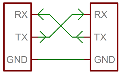
first we ll make all the  connection we need to get the information and the access to it as it's shown in the figure bellow


to make sure that a device from another network can connect to our system and command it wi choose PC2 to test the connectivity 
   - first we double click on it and then we go to desktop and click on command prompt

after opening the command prompt we ll test connectivity using the command ping with the adress that we gave it to our device 


next we go to desktop again and open web browser , then we go to our ip Adress. a username and a password are needed to log into our system (the default one is admin admin) but we can change it any time 


the devices state are  shown  and any mouvement will activate the motion detector turning the red light  into green.
and for the camera we can activate it anytime by clicking the red button 


Controlling Servo Motor

controlling Servo Motor


hello again my friends 
today's topic is about controlling a servo moteur using a microprocessor.
as we all know the  microcontroller  PIC,  that's why we gonna make a code that show us how we can control a servo using  PIC
for that every one who wanna try it must have Proteus and mikroc pro for PIC (download link in the end of  article)


first what's a servo ? and how it works ?


A servomotor is a rotary actuator or linear actuator that allows for precise control of angular or linear position, velocity and acceleration. It consists of a suitable motor coupled to a sensor for position feedback. It also requires a relatively sophisticated controller, often a dedicated module designed specifically for use with servomotors.


Servomotors are not a specific class of motor although the term servomotor is often used to refer to a motor suitable for use in a closed-loop controlsystem.


Servomotors are used in applications such as robotics, CNC machinery or automated manufacturing.(wikipedia)


code

void servoRotate0() //0 Degree
{
  unsigned int i;
  for(i=0;i<50;i++)
  {
    PORTB.F0 = 1;
    Delay_us(800);
    PORTB.F0 = 0;
    Delay_us(19200);
  }
}

void servoRotate90() //90 Degree
{
  unsigned int i;
  for(i=0;i<50;i++)
  {
    PORTB.F0 = 1;
    Delay_us(1500);
    PORTB.F0 = 0;
    Delay_us(18500);
  }
}

void servoRotate180() //180 Degree
{
  unsigned int i;
  for(i=0;i<50;i++)
  {
    PORTB.F0 = 1;
    Delay_us(2200);
    PORTB.F0 = 0;
    Delay_us(17800);
  }
}

void main()
{
  TRISB = 0; // PORTB as Ouput Port
  do
  {

    servoRotate90(); //90 Degree
    Delay_ms(2000);
    servoRotate0(); //0 Degree
    delay_ms(2000);
    servoRotate180(); //180 Degree
    Delay_ms(2000);
    servoRotate0(); //0 Degree
    delay_ms(2000);


  }while(1);
}


simulation 


vendredi 2 février 2018

Serial In Arduino

Arduino Serial (UART and USART)


Arduino has a built in Universal Synchronous Asynchronous Receiver Transmitter (USART) hardware that allows to communicate with a wide range of serial devices such as memory chips, LCDs, personal computers, etc. The USART module has two modes of operation: synchronous (requires a synchronized clock between the transmitter and receiver) and asynchronous (no synchronization clock required). As the asynchronous mode is more popular, we will focus today on this and will establish a two way serial data link between the Arduino and a PC.


Serial communications are used in microcontroller-based systems, mostly due to the scarcity of available I/O pins. Besides for long distance communications, serial data transfer is more simple and cost effective as the required hardware connections in the data link can be reduced to three (Tx, Rx, and Gnd).

in this tutorial  we ll show you a simple use of serial of  2 Arduino   which will show us that we are connected and the serial is ready to recieve an information

for that we ll need :
              - 2 Arduino
              - LED
              - Button
              - 330  resistance
              - 10K resistance


//Master code
int bt=10;

void setup() {
Serial.begin(9600);
pinMode(bt,INPUT);
}
void loop() {
  if (int r=digitalRead(bt)==1) {
Serial.print('H');
delay(1000);
  }
  else {
Serial.print('L');
delay(1000);
}
}


//Reciever code
const int led = 13;
int car1;


void setup() {
  Serial.begin(9600);
  pinMode(led, OUTPUT);
    }
 
 
void loop() {
   if (Serial.available() > 0) {
     car1 = Serial.read();
     if (car1 == 'H') {
     digitalWrite(led, HIGH);
     }
     if (car1 == 'L') {
       digitalWrite(led, LOW);
     }
   }
}
   

figure


lundi 22 janvier 2018

LCD with 4-bit or with 8-bit

LCD


LCD (Liquid Crystal Display) screen is an electronic display module and find a wide range of applications. A 16x2 LCD display is very basic module and is very commonly used in various devices and circuits. These modules are preferred over seven segments and other multi segment LEDs. The reasons being: LCDs are economical; easily programmable; have no limitation of displaying special & even custom characters (unlike in seven segments), animations and so on.

A 16x2 LCD means it can display 16 characters per line and there are 2 such lines. In this LCD each character is displayed in 5x7 pixel matrix. This LCD has two registers, namely, Command and Data.
The command register stores the command instructions given to the LCD. A command is an instruction given to LCD to do a predefined task like initializing it, clearing its screen, setting the cursor position, controlling display etc. The data register stores the data to be displayed on the LCD. The data is the ASCII value of the character to be displayed on the LCD.


Pin Diagram


Lcd in 4-bit mode

  • Commands used to initialize the 4-bit lcd mode To initialize character lcd in 4 bit mode we send value hex 0x20 to command register of lcd. 0x20 tells the lcd controller that we want to communicate in 4-bit mode. Lcd is 1 line (has 1 row) and we want character shape displayed in 5x7 matrix.
  • If our character lcd has 2 lines (rows) we will send 0x28 instead of 0x20. It tells the lcd controller that we want 4 bit communication and character size is between 5x7 dot matrix.
  • 4-bit mode make use of only just four data pins D4-D5-D6-D7.
  • In 4-bit mode character is displayed on lcd in two pulse signals. First the higher four nibbles of a character are sent to the lcd with an enable stroke. Than the lower four nibbles are send with enable stroke.
  • Since two pulse (enable) signals are required to display a single character so 4-bit mode latency time is high.

Lcd in 8-bit mode

Commands used to initialize the 8-bit lcd mode are
  • To initialize character lcd in 8-bit mode we send vale hex 0x30 to command register of lcd. 0x30 tells lcd that we want to communicate in 8-bit mode. Lcd is 1 line (has 1 row) and we want character shape displayed in 5x7 matrix. 
  • If our character lcd has 2 lines (rows) we will send 0x38 instead of 0x20. It tells the lcd controller that we want 4 bit communication and character size is between 5x7 dot matrix.
  • In 8-bit mode only one pulse signal is required to display a character on lcd.
  • Thus it is faster than 4-bit mode.

this is the explanation of functioning of 2 mode


mercredi 17 janvier 2018

LabView

LabVIEW For Beginner 


Laboratory Virtual Instrument Engineering Workbench (LabVIEW) is a system-design platform and development environment for a visual programming language from National Instruments.

The graphical language is named "G"; not to be confused with G-code. Originally released for the Apple Macintosh in 1986, LabVIEW is commonly used for data acquisition, instrument control, and industrial automation on a variety of operating systems(OSs), including Microsoft Windows, various versions of Unix, Linux, and macOS.

The latest versions of LabVIEW are LabVIEW 2017 and LabVIEW NXG 1.0, released in May 2017.


How to use labview


as we all know every program is opened by a double click , but each one has it's own interface.
on labview we have  this start page as it's shown in image 1 . this page show us our VI's and projects and also we can make a new file with it .


you can either open a blanck VI or a blanck project, but a blanck project is always more professional in work.

after opening it a new window will show up, you make a right-click on my computer and then we click on new VI(image2) . A new  window will show up(image3).


image 1


image 2


image 3


Front Panel

the front panel represent the HMI of labview, it has all the controls and the indicator, also we can found other data as arrays,images,...
this window make  the program using easier.
a right click show us the  contols menu as it's shown 


Block Diagram


this one is for programming our projects  and test it. but ... 
how we could make aprogram if we can write nothing on it ??!!

well this is the benefit of 'G' code, every thing is graphical
a right click show us the  functions  menu as it's shown  


as a start we ll make a simple VI which is calculate the sum of two numbers and display the result 


VI creation

  • Select: New VI (VirtualInstrument) 
  •  Select the front panel (gray) 
  •  right click → Commands 
  •  Move the mouse to 'Numeric' 

  •  A sub-window appears with numerical controls

Digital indicator

  •  Select 'digital indicator' (top left): move the mouse over it then left click
The digital indicator will display the result.

  • The cursor changes → main 
  •  Move the cursor to the front (gray) → double dotted box 
  •  Move this box to the desired position (left click)
  •  A default label ('Digital') is automatically created and highlighted 
  •  You can change the text immediately (for example: 'result') 
  •  You can also change the label later

Basic VI Example


Diagram (the operational part)

  •  Visualize the diagram <ctrl + E> to move from face to face ↔diagram 
  •  LabVIEWa placed a terminal on the diagram that is linked to the indicator placed on the front panel 
  •  You can move this terminal where you want on the diagram, it does not change anything on the front 
 By double clicking 
  •  on a front panel object → diagram terminal 
  •  on diagram terminal → front panel object


DBL is the type of output (real double)
 We can change this type later


Add a function

  •  Always on diagram, <right click> → the function palette appears 
  • Move the mouse → on numerical → the palette "numerical" appears with the mathematical functions 
  •  Click on the function "add" 
  •  Move the mouse towards the diagram → on see the function under the cursor in the shape of a hand 
  •  Place the cursor on the left of the indicator terminal 'result' 
  •  <left click> to set the function
We will now add the mathematical addition function.

Add constants

  •  Always on diagram, <right click> → the function palette appears 
  •  Move the mouse → on numerical → the palette "numerical" appears with the mathematical functions 
  •  Click on the function "numerical constant" 
  •  Move the mouse towards the diagram → we see the function under the cursor in the shape of a hand 
  •  Place the cursor on the left the operator 'sum' 
  •  <left click> to put the function 
  •  change the value of the constant to1 
  •  add a second constant = 3

wiring

  •  In the tool palette <shift + right click>, select the wiring tool (like a spool of thread) the cursor changes shape (coil) 
  •  position the cursor on the first constant → it flashes 
  •  <left click >, move the mouse → dashed line 
  •  Move the cursor to the 'add' function (+) 
  •  ...
  •  When the cursor arrives on the function, it starts to flash under the cursor at the connection terminals 
  •  Short connection lines also appear 
 Standard convention:
    •  input terminals on the left 
    •  output terminals on the right 

  •  Click on the connector top left 
  •  The cable is orange solid: valid wiring

Wiring -directions

  •  The cables always go horizontally or vertically, never diagonally 
  •  By default, there is a change of direction by cable, but 
    •  You can change the initial direction (horizontal or vertical) by pressing <space bar> 
    •  On can impose intermediate points by <left click>

Complete the wiring of the function

  •  Wire the second constant to the function (+) 
  •  Wire the output terminal of this function to the 'result' indicator

diagram completed


and now you completed your first VI on LabVIEW .
enjoy reading and learning