vendredi 16 février 2018

TFT Screen

TFT Screen with Arduino


hello guys thank you for returning back again and i hope you enjoy today's article

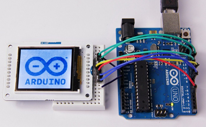
today we will connect a TFT Screen with Arduino and undrestand how we can write a message or changing the background color .

for that we need to know some basics as the TFT pins and how we can connect it to arduino . Also we will use the TFT library wich give us a specific wiring which it depends on the type of our board .


TFT


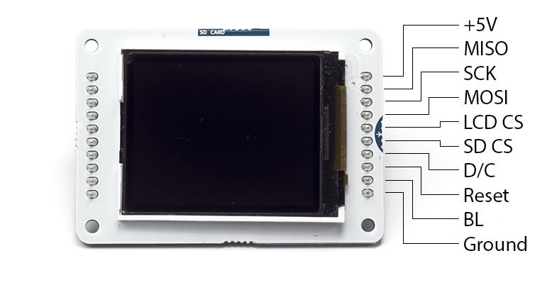
this figure show us the different function of each pin of our TFT screen 


Connecting TFT Screen

the TFT library has a specific pins to connect with our screen. we ll take the arduino UNO and MEGA for example.


    with Arduino UNO 


+5V:+5V
MISO:pin 12
SCK:pin 13
MOSI:pin 11
LCD CS:pin 10
SD CS:pin 4
D/C:pin 9
RESET:pin 8
BL:+5V
GND:GND


with Arduino MEGA

+5V:+5V
MISO:50 on Mega 2560 (Miso on ADK)
SCK:52 on Mega 2560 (Sck on ADK)
MOSI:51 on Mega 2560 (Mosi on ADK)
LCD CS:pin 10
SD CS:pin 4
D/C:pin 9
RESET:pin 8
BL:+5V
GND:GND


 we ll today use the TFT to test if a device is detected or not. 


Code

#include <TFT.h>  // Arduino LCD library
#include <SPI.h>

#define cs   10
#define dc   9
#define rst  8

int dev=2;
int Read;
String str1 = "detected";
String str2 = "not detected";
TFT TFTscreen = TFT(cs, dc, rst);

char strc1[13];

void setup() {

  pinMode(dev,INPUT);
  TFTscreen.begin();

  TFTscreen.background(255, 0, 0);


  TFTscreen.stroke(0, 0, 0);
  TFTscreen.setTextSize(2);
  TFTscreen.text("Device \n ", 0, 0);
  TFTscreen.setTextSize(2);
}

void loop() {

  Read=digitalRead(dev);
  
if (Read==HIGH) {
  str1.toCharArray(strc1, 13);

  TFTscreen.stroke(0, 0, 0);
  TFTscreen.text(strc1, 0, 20);
}
else {
  str2.toCharArray(strc1, 13);

  TFTscreen.stroke(0, 0, 0);
  TFTscreen.text(strc1, 0, 20);
}
  delay(1000);
  TFTscreen.stroke(255,0,0);
  TFTscreen.text(strc1, 0, 20);
}


lundi 12 février 2018

Internet of Things

Internet of Things (IoT)


hello everyone thank's for returning back and i hope you are enjoying reading my articles. today topic will be the Internet of Things (IoT).


we ll first start by a definition and then we ll talk about advantages and how to use it to get aconnected world together.


Definition


The Internet of Things (IoT) is a system of interrelated computing devices, mechanical and digital machines, objects, animals or people that are provided with unique identifiers and the ability to transfer data over a network without requiring human-to-human or human-to-computer interaction.


The first thing we ll ask about it, is the meaning of a thing.A thing can be a person, a car, a watch,... or any other natural or man-made object that can be assigned an IP address and provided with the ability to transfer data over a network.


why using IoT ?

the uses of IoT, make our lifes easier, the things will tell us the problem without even think about it, "it will take care of us" even in the unreachebale places like forests and mountains .

as an example we have today things(devices) that alert us if there's a fire in somewhere by notifying our cellphones our computer or eve our smart watch .


most common Devices of IoT

-The ESP8266 is a low-cost Wi-Fi microchip with full TCP/IP stack and microcontroller capability produced by Shanghai-based Chinese manufacturer, Espressif Systems.(wikipédia)


  - NodeMCU is an open source IoT platform.It includes firmware which runs on the ESP8266 Wi-Fi SoC from Espressif Systems, and hardware which is based on the ESP-12 module. The term "NodeMCU" by default refers to the firmware rather than the dev kits. The firmware uses the Lua scripting language. It is based on the eLua project, and built on the Espressif Non-OS SDK for ESP8266. It uses many open source projects, such as lua-cjson,and spiffs.


program of IoT simulation


- Packet Tracer est un simulateur de matériel réseau Cisco (routeurs, commutateurs). Cet outil est créé par Cisco Systems qui le fournit gratuitement aux centres de formation, étudiants et diplômés participant, ou ayant participé, aux programmes de formation Cisco (Cisco Networking Academy).

the last version is 7.1.0.0222 the program is using usually for network configuration but the last version adds too many featuring like micro-processer which we can program it using python or JS and we can better get into IoT with it and understand some network protocols.

the program contain too much helpful examples to start with it

we ll today make a simple program that notice us if there's somebody at our homegate for example with the possibility of switch on/off a camera to see that person.

first we ll make all the  connection we need to get the information and the access to it as it's shown in the figure bellow


to make sure that a device from another network can connect to our system and command it wi choose PC2 to test the connectivity 
   - first we double click on it and then we go to desktop and click on command prompt

after opening the command prompt we ll test connectivity using the command ping with the adress that we gave it to our device 


next we go to desktop again and open web browser , then we go to our ip Adress. a username and a password are needed to log into our system (the default one is admin admin) but we can change it any time 


the devices state are  shown  and any mouvement will activate the motion detector turning the red light  into green.
and for the camera we can activate it anytime by clicking the red button 


Controlling Servo Motor

controlling Servo Motor


hello again my friends 
today's topic is about controlling a servo moteur using a microprocessor.
as we all know the  microcontroller  PIC,  that's why we gonna make a code that show us how we can control a servo using  PIC
for that every one who wanna try it must have Proteus and mikroc pro for PIC (download link in the end of  article)


first what's a servo ? and how it works ?


A servomotor is a rotary actuator or linear actuator that allows for precise control of angular or linear position, velocity and acceleration. It consists of a suitable motor coupled to a sensor for position feedback. It also requires a relatively sophisticated controller, often a dedicated module designed specifically for use with servomotors.


Servomotors are not a specific class of motor although the term servomotor is often used to refer to a motor suitable for use in a closed-loop controlsystem.


Servomotors are used in applications such as robotics, CNC machinery or automated manufacturing.(wikipedia)


code

void servoRotate0() //0 Degree
{
  unsigned int i;
  for(i=0;i<50;i++)
  {
    PORTB.F0 = 1;
    Delay_us(800);
    PORTB.F0 = 0;
    Delay_us(19200);
  }
}

void servoRotate90() //90 Degree
{
  unsigned int i;
  for(i=0;i<50;i++)
  {
    PORTB.F0 = 1;
    Delay_us(1500);
    PORTB.F0 = 0;
    Delay_us(18500);
  }
}

void servoRotate180() //180 Degree
{
  unsigned int i;
  for(i=0;i<50;i++)
  {
    PORTB.F0 = 1;
    Delay_us(2200);
    PORTB.F0 = 0;
    Delay_us(17800);
  }
}

void main()
{
  TRISB = 0; // PORTB as Ouput Port
  do
  {

    servoRotate90(); //90 Degree
    Delay_ms(2000);
    servoRotate0(); //0 Degree
    delay_ms(2000);
    servoRotate180(); //180 Degree
    Delay_ms(2000);
    servoRotate0(); //0 Degree
    delay_ms(2000);


  }while(1);
}


simulation 


vendredi 2 février 2018

Serial In Arduino

Arduino Serial (UART and USART)


Arduino has a built in Universal Synchronous Asynchronous Receiver Transmitter (USART) hardware that allows to communicate with a wide range of serial devices such as memory chips, LCDs, personal computers, etc. The USART module has two modes of operation: synchronous (requires a synchronized clock between the transmitter and receiver) and asynchronous (no synchronization clock required). As the asynchronous mode is more popular, we will focus today on this and will establish a two way serial data link between the Arduino and a PC.


Serial communications are used in microcontroller-based systems, mostly due to the scarcity of available I/O pins. Besides for long distance communications, serial data transfer is more simple and cost effective as the required hardware connections in the data link can be reduced to three (Tx, Rx, and Gnd).

in this tutorial  we ll show you a simple use of serial of  2 Arduino   which will show us that we are connected and the serial is ready to recieve an information

for that we ll need :
              - 2 Arduino
              - LED
              - Button
              - 330  resistance
              - 10K resistance


//Master code
int bt=10;

void setup() {
Serial.begin(9600);
pinMode(bt,INPUT);
}
void loop() {
  if (int r=digitalRead(bt)==1) {
Serial.print('H');
delay(1000);
  }
  else {
Serial.print('L');
delay(1000);
}
}


//Reciever code
const int led = 13;
int car1;


void setup() {
  Serial.begin(9600);
  pinMode(led, OUTPUT);
    }
 
 
void loop() {
   if (Serial.available() > 0) {
     car1 = Serial.read();
     if (car1 == 'H') {
     digitalWrite(led, HIGH);
     }
     if (car1 == 'L') {
       digitalWrite(led, LOW);
     }
   }
}
   

figure