lundi 22 janvier 2018

LCD with 4-bit or with 8-bit

LCD


LCD (Liquid Crystal Display) screen is an electronic display module and find a wide range of applications. A 16x2 LCD display is very basic module and is very commonly used in various devices and circuits. These modules are preferred over seven segments and other multi segment LEDs. The reasons being: LCDs are economical; easily programmable; have no limitation of displaying special & even custom characters (unlike in seven segments), animations and so on.

A 16x2 LCD means it can display 16 characters per line and there are 2 such lines. In this LCD each character is displayed in 5x7 pixel matrix. This LCD has two registers, namely, Command and Data.
The command register stores the command instructions given to the LCD. A command is an instruction given to LCD to do a predefined task like initializing it, clearing its screen, setting the cursor position, controlling display etc. The data register stores the data to be displayed on the LCD. The data is the ASCII value of the character to be displayed on the LCD.
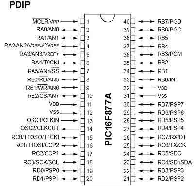


Pin Diagram


Lcd in 4-bit mode

  • Commands used to initialize the 4-bit lcd mode To initialize character lcd in 4 bit mode we send value hex 0x20 to command register of lcd. 0x20 tells the lcd controller that we want to communicate in 4-bit mode. Lcd is 1 line (has 1 row) and we want character shape displayed in 5x7 matrix.
  • If our character lcd has 2 lines (rows) we will send 0x28 instead of 0x20. It tells the lcd controller that we want 4 bit communication and character size is between 5x7 dot matrix.
  • 4-bit mode make use of only just four data pins D4-D5-D6-D7.
  • In 4-bit mode character is displayed on lcd in two pulse signals. First the higher four nibbles of a character are sent to the lcd with an enable stroke. Than the lower four nibbles are send with enable stroke.
  • Since two pulse (enable) signals are required to display a single character so 4-bit mode latency time is high.

Lcd in 8-bit mode

Commands used to initialize the 8-bit lcd mode are
  • To initialize character lcd in 8-bit mode we send vale hex 0x30 to command register of lcd. 0x30 tells lcd that we want to communicate in 8-bit mode. Lcd is 1 line (has 1 row) and we want character shape displayed in 5x7 matrix. 
  • If our character lcd has 2 lines (rows) we will send 0x38 instead of 0x20. It tells the lcd controller that we want 4 bit communication and character size is between 5x7 dot matrix.
  • In 8-bit mode only one pulse signal is required to display a character on lcd.
  • Thus it is faster than 4-bit mode.

this is the explanation of functioning of 2 mode


mercredi 17 janvier 2018

LabView

LabVIEW For Beginner 


Laboratory Virtual Instrument Engineering Workbench (LabVIEW) is a system-design platform and development environment for a visual programming language from National Instruments.

The graphical language is named "G"; not to be confused with G-code. Originally released for the Apple Macintosh in 1986, LabVIEW is commonly used for data acquisition, instrument control, and industrial automation on a variety of operating systems(OSs), including Microsoft Windows, various versions of Unix, Linux, and macOS.

The latest versions of LabVIEW are LabVIEW 2017 and LabVIEW NXG 1.0, released in May 2017.


How to use labview


as we all know every program is opened by a double click , but each one has it's own interface.
on labview we have  this start page as it's shown in image 1 . this page show us our VI's and projects and also we can make a new file with it .


you can either open a blanck VI or a blanck project, but a blanck project is always more professional in work.

after opening it a new window will show up, you make a right-click on my computer and then we click on new VI(image2) . A new  window will show up(image3).


image 1


image 2


image 3


Front Panel

the front panel represent the HMI of labview, it has all the controls and the indicator, also we can found other data as arrays,images,...
this window make  the program using easier.
a right click show us the  contols menu as it's shown 


Block Diagram


this one is for programming our projects  and test it. but ... 
how we could make aprogram if we can write nothing on it ??!!

well this is the benefit of 'G' code, every thing is graphical
a right click show us the  functions  menu as it's shown  


as a start we ll make a simple VI which is calculate the sum of two numbers and display the result 


VI creation

  • Select: New VI (VirtualInstrument) 
  •  Select the front panel (gray) 
  •  right click → Commands 
  •  Move the mouse to 'Numeric' 

  •  A sub-window appears with numerical controls

Digital indicator

  •  Select 'digital indicator' (top left): move the mouse over it then left click
The digital indicator will display the result.

  • The cursor changes → main 
  •  Move the cursor to the front (gray) → double dotted box 
  •  Move this box to the desired position (left click)
  •  A default label ('Digital') is automatically created and highlighted 
  •  You can change the text immediately (for example: 'result') 
  •  You can also change the label later

Basic VI Example


Diagram (the operational part)

  •  Visualize the diagram <ctrl + E> to move from face to face ↔diagram 
  •  LabVIEWa placed a terminal on the diagram that is linked to the indicator placed on the front panel 
  •  You can move this terminal where you want on the diagram, it does not change anything on the front 
 By double clicking 
  •  on a front panel object → diagram terminal 
  •  on diagram terminal → front panel object


DBL is the type of output (real double)
 We can change this type later


Add a function

  •  Always on diagram, <right click> → the function palette appears 
  • Move the mouse → on numerical → the palette "numerical" appears with the mathematical functions 
  •  Click on the function "add" 
  •  Move the mouse towards the diagram → on see the function under the cursor in the shape of a hand 
  •  Place the cursor on the left of the indicator terminal 'result' 
  •  <left click> to set the function
We will now add the mathematical addition function.

Add constants

  •  Always on diagram, <right click> → the function palette appears 
  •  Move the mouse → on numerical → the palette "numerical" appears with the mathematical functions 
  •  Click on the function "numerical constant" 
  •  Move the mouse towards the diagram → we see the function under the cursor in the shape of a hand 
  •  Place the cursor on the left the operator 'sum' 
  •  <left click> to put the function 
  •  change the value of the constant to1 
  •  add a second constant = 3

wiring

  •  In the tool palette <shift + right click>, select the wiring tool (like a spool of thread) the cursor changes shape (coil) 
  •  position the cursor on the first constant → it flashes 
  •  <left click >, move the mouse → dashed line 
  •  Move the cursor to the 'add' function (+) 
  •  ...
  •  When the cursor arrives on the function, it starts to flash under the cursor at the connection terminals 
  •  Short connection lines also appear 
 Standard convention:
    •  input terminals on the left 
    •  output terminals on the right 

  •  Click on the connector top left 
  •  The cable is orange solid: valid wiring

Wiring -directions

  •  The cables always go horizontally or vertically, never diagonally 
  •  By default, there is a change of direction by cable, but 
    •  You can change the initial direction (horizontal or vertical) by pressing <space bar> 
    •  On can impose intermediate points by <left click>

Complete the wiring of the function

  •  Wire the second constant to the function (+) 
  •  Wire the output terminal of this function to the 'result' indicator

diagram completed


and now you completed your first VI on LabVIEW .
enjoy reading and learning 


lundi 8 janvier 2018

OPEN DRAIN

Open Drain


The term “open drain” means there’s a current sink, but on a FET device, for example, a MOSFET. (A MOSFET is like a transistor that can handle higher voltages but operates in much the same way.)


the main point in the term open drain is that part of the output transistor is directly brought out to a pin that is external to the IC package.


Open drain devices sink current when controlled to one state and have no current flow (i.e., output a high impedance state) in the other state. It is fairly common to use open-drains together with a pull-up resistor. The pull-up resistor is connected to high (supply voltage) at one end and connected to one or more external pins of the open-drain devices all connected together. Thus, if any one of the open-drain devices is set to sink current, current flow for all of the devices gets sunk to ground, since they are all connected at the same point.


that holds the signal line high until a device on the wire sinks enough current to pull the line low. Many devices can be attached to the signal wire. If all devices attached to the wire are in their non-active state, the pull-up will hold the wire at a high voltage. If one or more devices are in the active state, the signal wire voltage will be low. Basically, the circuit has a resistor between it and the path to 5V (pull-up resistor). Pull-up resistors are used so that when the FET (transistor) is “OFF” the wire will float to the high voltage, which is usually supply voltage for the circuit.


some of you may say "where we can found it?" or "what's the link between it and the programmable IC like pic?"

well the answer is that most of PIC have an open drain .


how we control it ?


as we know every pic has ports to configure as outputs or inputs by setting the TRISX (X can be from A to E, it depend on the ref. of PIC) . we used to put '0' as output and '1' as input .


well that is not the case with the TRISX where we have the open drain. all bits are configured as we say unless for the open drain bit. a '0' means level low (0 V) while a '1' means HIGH (5V)


to better undrestand the function of the open drain, we ll take PIC16F877A as an example.


this PIC has 5 ports from PORTA to PORTE, which are configured by setting TRISX of each port

the open drain is present at RA4-pin so when you are working on this port you should either miss it

or use it as a drain


RA4 is the 2nd bit starting from MSB so in mikroc you just write "TRISA=0b000000" to have a level low on RA4 pin or "TRISA=0b010000" to have a level high


jeudi 4 janvier 2018

my first PIC project


as we know all every embedded system need a software to defign the function of our system . for the PIC we ll use Mikro c for coding and proteus isis for the simulation

the first code we wrote in C is "hello world", today we ll write our mikro c "hello world"

this first code will be about flashing a led . we can use this code also to test our PIC .

we start by a very simple code to make sure that we can write the code correctly and to compile it and loaded it inside the pic.


in this session we ll connect a LED to one of the port pin of pic16F877A and flash it continuously with 1 sec duration .


some software well be needed so i recommand you all to install

- proteus isis 8.0 (link in download page)

- mikroc pro for pic (link in download page)


in this session we ll also know about


digital I/O ports (PORTD) of PIC16F877A
direction control registers, TRISD
special function registers CMCON and ADCON1


software


Open a new project window in mikroC and select Device Name as PIC16F877A. Next assign 4.0 MHz to Device Clock. Go to next and provide the project name and the path of the folder. It is always a good practice to have a separate folder for each project. Create a folder named myfirstpicproj and save the project inside it with a name (say, blink). The mikroC project file has .mccpi extension. The next window is for “Add File to Project “. Leave it blank (there are no files to add to this project) and click next. The next step is to include libraries, select Include All option. Next, click Finish button. You will see a program window with a void main() function already included.


code


// Define LED @ RD1

sbit LED at RD1_bit;

void main() {

ADCON1 = 7;

CMCON = 0x07 ; // Disbale comparators

TRISD.f1= 0; // PORTD All Outputs


do {

LED = 1;

Delay_ms(1000);

LED = 0;

Delay_ms(1000);

} while(1); // Infinite Loop


}


after compiling our code we need to simulate and see the function of our system

first you need to open proteus isis and add all the component (in our case we need crystal, pic16F877A, resistance, LED, and capacitors)

next we route them to get our circuit


double click on PIC to edit it


when this page appear we click on the yellow folder and go to the path where we save our projet and select projectname.hex


enjoy watching your first program :D

mardi 2 janvier 2018

what's an embedded system


Computer systems are everywhere. They fall into essentially two separate categories. The first and most obvious is that of the desktop computer, they are designed to be flexible and to meet a wide range of user needs.


The second type of computer is the embedded computer (or embedded system), a computer that is embedded into a bigger electronics system and repeatedly carrying out a particular function, often going completely unrecognized by the system’s user.


Definition: An embedded system is a computer system that is built to control one or a few dedicated functions, and is not designed to be programmed by the end user in the same way that a desktop computer is.


if we ask some one how many computer he have in his home probably he will count just his desktop computer and his laptop. However, computers have always been embedded into all sorts of everyday items like washing machine, TV, ....


In most cases, an embedded system is used to replace an application-specific electronics in the consumer products. By doing so, most of the system’s functionality is encapsulated in the firmware that runs the system, and it is possible to change and upgrade the system by changing the firmware, while keeping the hardware same. This reduces the cost of production even lower because many different systems can share the same hardware base and the functionality is determined by the firmware loaded into them.


this is a short list of embedded systems

Cell phones, digital cameras, battery chargers, digital thermostats, traffic light controllers, digital watches, washers and dryers, ovens, fax machines, printers, televisions, DVD players, factory control, satellite phones, modems, network cards, pagers, portable video games, photocopiers, home security systems, mp3 players, ipod, cruise control, anti-lock brakes, air bag control

they are everywhere !!


inside every embedded system we have 3 principle parts : processor, memory, and Peripherals which can any embedded system communicate with the outside


those peripherals are

- digital inputs and outputs

- serial interfaces

- analog to digital convertor

- keypads


as a conclusion we can say embedded system have many advantages

The big advantage of using an them to replace a dedicated electronics circuit is the protection of intellectual property. If your design is completely hardware based, it is easier to steal the design. All you need is to identify the circuit components and trace the tracks on the circuit board. With an embedded system, the hardware can be identified but the software, which really supplies the system’s functionality, can be hidden and more difficult to crack.