HC-05 ==> HC-05 || HC-06
hi guys it's been a while. nice to see you again and i hope you are fine.
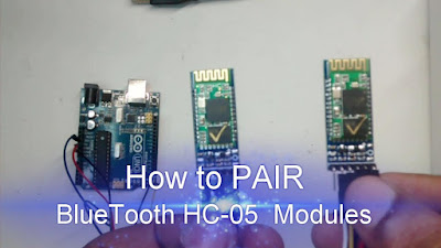
today we gonna show you how to connect 2 bluetooth devices and have a data transfer between them
first of all we'll explain differences between HC-05 and HC-06
Bluetooth is a wireless technology standard for exchanging data over short distances (using short-wavelength UHF radio waves in the ISM band from 2.4 to 2.485 GHz) from fixed and mobile devices, and building personal area networks (PANs). Range is approximately 10 Meters (30 feet).
- HC-05 is a more capable module that can be set to be either Master or Slave.
- HC-06 is a Slave only device. (It looks physically just like the HC-05).(Note: Now HC-06 not cheaper)
- These small ( 3 cm long) modules run on 3.3V power with 3.3V signal levels, They have no pins and usually solder to a larger board. (See example below)
- The module has two modes of operation, Command Mode where we can send AT commands to it and Data Mode where it transmits and receives data to another bluetooth module.
- "Breakout" Boards that make these easy to use are available and recommended. These mount the sub-module like that shown on the right on a slightly larger board. NOTE: Sellers often label them "HC-05" or "HC-06", but they have some other model number on the reverse side. Most of these boards support operation at 5V power and interface to 5V Arduino signal levels with some technique of level shifting.
HC-05 :
HC-05 PinOut (Right) :
- KEY: If brought HIGH before power is applied, forces AT Command Setup Mode. LED blinks slowly (2 seconds)
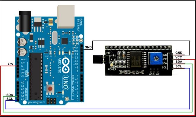
- VCC: +5 Power
- GND: System / Arduino Ground
- TXD: Transmit Serial Data from HC-05 to Arduino Serial Receive. NOTE: 3.3V HIGH level: OK for Arduino
- RXD: Receive Serial Data from Arduino Serial Transmit
- STATE: Tells if connected or not
The module has two modes of operation, Command Mode where we can send AT commands to it and Data Mode where it transmits and receives data to another bluetooth module.
The default mode is DATA Mode, and this is the default configuration, that may work fine for many applications:
- Baud Rate: 9600 bps, Data : 8 bits, Stop Bits: 1 bit, Parity : None, Handshake: None
- Passkey: 1234
- Device Name: HC-05
Bluetooth Master Mode:To configure the module as Bluetooth Master and to pair with another bluetooth module follow these steps. First we need to put the module into command mode as above by pulling the CMD pin high before power on. (Use the BlueToothCommandUtility for this.)
Enter these commands in order:
we must set those AT commands to every devices we'll use
- AT+RMAAD Clear any paired devices
- AT+ROLE=1 Set mode to Master (=0 set mode to slave).
- AT+RESET After changing role, reset is required
- AT+CMODE=0 Allow connection to any address (I have been told this is wrong and CMODE=1 sets "any address"
- AT+INQM=0,5,5 Inquire mode - Standard, stop after 5 devices found or after 5 seconds
- AT+PSWD=1234 Set PIN. Should be same as slave device
- AT+INIT Start Serial Port Profile (SPP) ( If Error(17) returned - ignore as profile already loaded)
for the slave device there is no more commands but waiting to be paired but to the master a few other commands must be set .
these commands are :
- AT+INQ Start searching for devices
- AT+PAIR=<address>,<timeout> The timeout is in seconds and if you need to type in the pin on the slave device you need to give enough time to do this.
- AT+BIND=<address> Set bind address to the slave address
- AT+CMODE=0 (Correction!) Allow master to ONLY connect to bound address (slave). This allows the master to automatically connect to the slave when switched on
- AT+LINK=<address> Connect to slave.
after linking devices each device will blink 2 times every 2 seconds. this blinking assure the good function of our communication .