Hello guys , here we are again to learn utilisation of another device. Today's device is Matrix of led.
First we gonna start by defining a matrix led, how it is build from inside, number of pins and how to connect it.
Matrix led
a matrix led is a display device, it's easy to use and it have many applications in real life, such as various types of electronic display panels and in other projects.
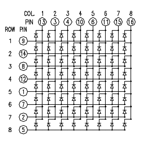
today we gonna use a 8x8 matrix. so we have a 64 led , it can be of any color (red, green, blue, ...) . this leds are wired as it's shown in the picture below (every row have a common anode and a different cathode and every colomn have a common cathode and a different anode ).
that's give us a 16 pin s to connect to our microcontroller but sometimes it's too much and we can't connect any other device with it so today we gonna show you two different ways to connect a matrix led. for this tutorial we will just connect it simply.
first let's start by defining the function of each pin
1:
R5
2:
R7
3:
C2
4:
C3
5:
R8
6:
C5
7:
R6
8:
R3
9:
R1
10:
C4
11:
C6
12:
R4
13:
C1
14:
R2
15:
C7
16:
C8
with R : row
C : col
connect matrix simply
we ll just connect the 16 matrix pins with our microcontroller(arduino in our case) directly
hey guys, nice to see you again and i hope you are enjoying reading my articles .
today topic is how to use PWM with microcontroller. we ll use PIC16F877A as our microcontroller, we ll discover what's PWM? how it works? and for what we need it?
PWM
A pulse width modulated (PWM) signal is a method of generating an analog signal using a digital source. A PWM signal consists of two main components that define its behavior: a duty cycle and a frequency. The duty cycle describes how long the signal is in the high (active) state as a percentage of the duration of a complete cycle. The frequency determines the speed at which the PWM cycles (for example, 1000 Hz would be 1000 cycles per second) and therefore how fast it goes from high to low and vice versa. By changing the state of a digital signal fast enough, and with a certain duty cycle, the output will appear to behave as a constant voltage analog signal when it powers devices.
How it works
Example: To create a 3V signal, given a digital source that can be high (active) at 5V or low (inactive) at 0V, you can use the PWM with a duty cycle of 60% to return 5V 60 % time. If the cycles of the digital signal are sufficiently short, the visible voltage on the output appears to be the average voltage. If the low voltage of the digital signal is 0 V (usually the case), the average voltage can be calculated by multiplying the high voltage of the digital signal by the duty cycle, ie 5 V x 0.6 = 3 V. A duty cycle of 80% would produce 4V, a 20%, 1V, and so on.
when using PIC the generation of PWM signal needs the module CCP (capture compare pwm) which uses generally TIMER2 of our PIC.
since the TIMER2 is on 8 bits, period resolution is 256 wich mean that high level(5v) is defined by 255 and low level (0v) is defined by 0.
Uses of PWM
PWM signals are used in a wide range of control applications. They are mainly used to control DC motors but can also be used to control valves, pumps, hydraulic systems and other mechanical parts. The frequency required for the PWM signal depends on the application and the response time of the powered system. Here are some applications and the minimum frequencies typically required for the PWM signal:
- Heating elements or systems with long response time: 10 to 100 Hz, or more.
- DC electric motors: 5 to 10 kHz or more.
- Power supplies or audio amplifiers: 20 to 200 kHz, or more.
example of PWM using PIC16F877A
for this example we ll need :
- PIC16F877A
- Crystal 20MHz
- Capacitor 15pF
- Lamp
- Switch
welcome guys, it's been awhile ,
today's topic is about making a simple vi, this vi will allow us to read data from arduino unsig the visa module for that we need to open a connection with the port defining Arduino then read data and show it as a graph
the main objectif is to read data from serial and make a graph with it